Building and Modding a MiniDox
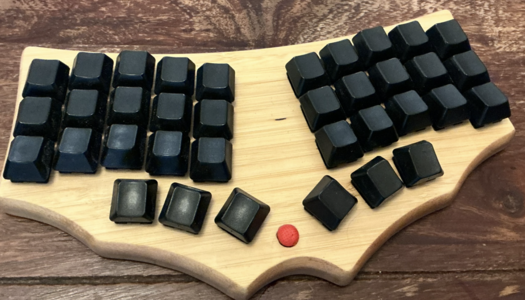
Thirty-six keys, one Teensy, and a TrackPoint in a wooden case.
After my previous post about my long-running ErgoDox experiments, I got some feedback from people wondering whether I had actually built another keyboard in all those years. Apparently, in the mechanical-keyboard world you’re supposed to build these things all the time, rather than spend a decade continuously modifying the same one. Point taken.
Starting with the MiniDox
I bought the parts from FalbaTech. The DIY package contained a nice wooden case, switches, diodes, and the other discrete components, but no microcontrollers.
The board seems to be designed for two Pro Micros, one on each half. I didn’t have any Pro Micros. I did, however, have a Teensy 2.0, based on the same the ATmega32U4 MCU.
There was also a good reason not to use two MCUs in the first place. I bought the MiniDox as a single-body keyboard. Since both halves share one case, running a few more wires from one side to the other isn’t much of a problem. Using two microcontrollers seemed like overkill.
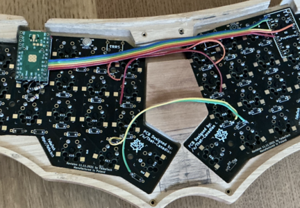
One Teensy, two hands
There was another reason for using my good old Teensy 2.0: the TrackPoint.
I’m a big TrackPoint fan, and my ErgoDox already has one. My TrackPoint code uses the ATmega32U4 USART hardware for PS/2 and needs pins D2 and D5 (as described in my PS/2 decoder post). The Teensy conveniently exposes them. The Pro Micro doesn’t seem to offer an easy way to reach these pins.
For anyone looking for the same module, useful search terms are SurnQiee TrackPoint or CCYLEZ TrackPoint on Amazon or AliExpress.
Apart from the Teensy’s power, ground, and reset, D2 and D5 were the only pins whose jobs were fixed in this build. The matrix signals could use whichever remaining Teensy pins made the wiring convenient. I use my own home-made keyboard firmware, so I could adapt its matrix configuration to match.
There was just one problem: the Teensy’s pins line up with the PCB holes intended for the Pro Micro, but the pin assignments don’t match. This time, however, I planned the whole thing before soldering the MCU. I knew which Teensy pins needed to go where. Some could be soldered directly into the holes beneath them. Where that didn’t work, I left the pin disconnected from its hole and instead routed it to the right signal with a short piece of wire.
I also had to flip the Teensy over to make it fit. It sits below the MiniDox PCB, where the Pro Micro would normally go, but with its component side facing the PCB. That leaves the USB connector sandwiched between the two boards.
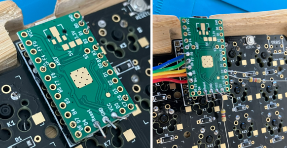
Teensy mounting (left) and wiring with the PS/2 resistors (right).
No modifications to the PCB were necessary. I didn’t have to cut a single trace or reroute anything on the board itself.
The Teensy just sees one larger matrix spanning the entire keyboard: four shared rows and ten columns, using fourteen GPIO pins. Here is the wiring for future reference, using AVR port names. The MiniDox PCB labels its Pro Micro mounting holes with the MCU pins that a Pro Micro would expose there. In the table, a label in the “Pro Micro hole” column means the Teensy pin is soldered directly into that hole. A dash means no connection is made to the PCB hole beneath the Teensy pin; the signal is wired separately.
| Signal | Teensy pin | Pro Micro hole |
|---|---|---|
| Top row | C7 | B6 |
| Home row | C6 | B2 |
| Bottom row | D6 | B5 |
| Thumb row | D7 | B4 |
| Left column 1 | B5 | — |
| Left column 2 | F6 | — |
| Left column 3 | F7 | D4 |
| Left column 4 | B6 | — |
| Left column 5 | B4 | — |
| Right column 1 | D0 | — |
| Right column 2 | B3 | F4 |
| Right column 3 | B1 | — |
| Right column 4 | B0 | — |
| Right column 5 | F5 | D1 |
| TrackPoint PS/2 | D2, D5 | — |
Soldering and cutting things
The soldering went surprisingly smoothly, although the results didn’t necessarily look any better. It was my first time using flux paste. Its main benefit was keeping the tiny diodes in place while I soldered them.
The TrackPoint also needed a home. There is quite a bit of space between the two thumb clusters, which seemed like a promising position: I wouldn’t have to move either hand much to reach it.
Fitting it into the case required some mechanical work. This finally gave me an excuse to replace my old cheap Tacklife rotary tool, which had apparently died of boredom after not being used for too long. I bought a corded Proxxon instead, so I won’t find myself with a dead battery after two years of storage in the basement.
The TrackPoint wasn’t the only part that needed more clearance. Even with the Teensy flipped over, I had to thin the inside of the bottom cover directly below the microcontroller before the case would close.
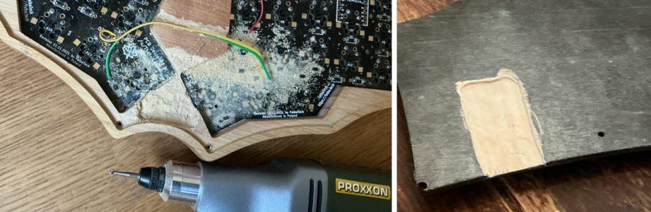
And once I had the hammer, everything started looking like a nail. So I also carved a channel for the row wires running between the two halves, just for fun.
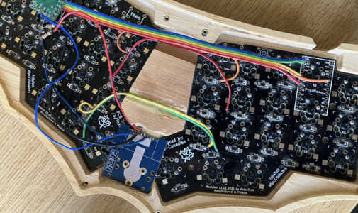
The TrackPoint’s PS/2 board sits below the thick wooden case. Even after grinding away material to bring it closer to the surface, I still needed an extension to bring the red cap up to a usable height.
I found a small plastic tube among my collection of spare wires, screws, and other things that might be useful one day. It was perhaps 4–5 mm wide, and I found a tiny screw that more or less fit inside it. I cut a section of tube about 3–4 mm long and enlarged its hole at one end to fit over the TrackPoint’s stick.
Then I shortened the screw and screwed it one or two turns into the other end of the tube. The total height of the assembled tube, screw, and red cap is 8 mm.
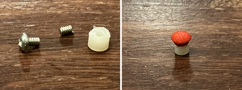
The nicest surprise came when I plugged everything in for the first time: it just worked. The complete matrix worked across both halves. Even the TrackPoint worked immediately!
That was almost disappointing. Almost.
Living with 36 keys
Getting the hardware working and actually liking the keyboard are, of course, two different things.
I’m still not completely convinced by the TrackPoint between the thumbs. On paper it seemed like a great position because it requires so little movement from the normal typing position. In practice, I’m not used to controlling the pointer with my thumb, let alone the side of my thumb. When moving the pointer toward the top left, I also tend to touch the innermost left thumb key. It’s usable, and I’m getting used to it, but it wasn’t instant love.
The bigger question might be whether a 36-key layout is for me at all. With so
few keys, you inevitably start making individual keys do more than one thing.
Home-row mods, tap-holds, layers, and all sorts of combinations become
important. Typing letters is fine, but as soon as I need something beyond the
basic keys, it gets harder. Something like $SOME_64& requires a whole series
of different key combinations, moving from the left hand to the right and back
again. I still regularly stop and think: hold on, what is the easiest way to
type this?
There was also an unexpected consequence: all these clever key behaviors turned out to be quite a challenge for my home-made keyboard firmware. Scanning a matrix and emitting ordinary key presses is one thing. Deciding whether a key was a tap or a hold, while other keys and modifiers are interacting with it, is quite another.
I have spent considerably more time thinking about that problem than I expected. But that’s material for another post.