Understanding Dannegger's Debouncer
Mechanical switches are electrically noisy. What the firmware of your keyboard
sees when a key is pressed is not a single clean 0 -> 1 transition, but a
rattling sequence of 0’s and 1’s, which eventually stabilizes. To turn this
flickering signal into a reliable pressed / released event, a firmware
typically inserts a debouncing routine.
In this post, I want to dissect Peter Dannegger’s debouncing routine: a tiny, bit-parallel algorithm. Even if you don’t plan writing a keyboard firmware yourself in the next days, take a look at this algorithm: it’s quite elegant.
1. Mechanical Contacts Bounce
When you press or release a mechanical switch (Cherry MX, Alps, Kailh, etc.), the metal contacts do not transition cleanly from open to closed or vice versa. This “bounce” happens in both directions (press and release) and can last anywhere between 1-10 ms depending on switch geometry, spring tension, lubrication, and force.
A microcontroller scanning the key matrix might observe:
Time (ms):   0   1   2   3   4   5   6
Raw signal:  0   1   0   1   0   1   1
If the firmware reacted to every raw transition, this would generate multiple press/release events for a single physical key press/release.
If you are like me and prefer seeing over simply believing, here is a simple measurement performed with the microcontroller in my keyboard for a single key press.
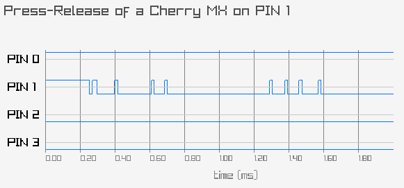
It does not show the real bouncing curve of the switch (that would require using an oscilloscope), but rather what the firmware would see for a single keypress. Note: the lines are initially high and a key press grounds the wire, so the transition is rather from 1 to 0 when pressing.
2. Dannegger’s Debounce
As I’ve mentioned in a previous post, I am slowly rewriting my keyboard firmware. My current debouncer is a hacky solution using a delay. In the search for a better solution, I’ve found this gem.
2.1. The Basis
When we read a different value on the wire, we don’t immediately change our mind
about the switch state, but rather record this information. Only after
consecutively reading that new value for N times, we flip the state bit.
So we keep one bit for the stable state plus a counter of log(N) bits to track
the number of consecutive diverging reads. Given the relatively low frequency of
microcontrollers, every read is typically performed ~2ms apart and 4 reads
should be sufficient to determine whether the signal is stable. Hence, a 2-bit
counter suffices.
This simple debouncing routine would be like this:
val = READ_PIN();
if (state == val) {
    count = 0;
} else {
    count++;
    if (count == N) {
        count = 0
        state = ~state
    }
}
We never really write the read value into the state. We just flip the state bit
when enough difference was observed – remember, val and state are 1-bit
variables.
When we want to keep track of every key on a keyboard, we simply use an array of (state, counter) pairs with 30-100 such pairs depending on how spartan your keyboard is.
2.2 The Intuition
Although memory space in microcontrollers is limited, tracking the debouncing state of 100 keys is not a problem in practice. Still, for the sake of explanation, let’s assume we want to pack counters together to reduce RAM usage a bit.
Our counters only need 2 bits. For 8 keys, we would store one state byte and
two counter bytes:
state  = s0 s1 s2 s3 s4 s5 s6 s7
count0 = c00 c01 c10 c11 c20 c21 c30 c31
count1 = c40 c41 c50 c51 c60 c61 c70 c71
Here, sK is the state bit of key K and cK0 and cK1 are its counter bits.
Now imagine the hassle of working with these merged 2-bit counters, incrementing them, resetting individual counters, checking for overflow, and deciding when to flip the state.
2.3 The Algorithm
Here enters Dannegger’s trick: We transpose the counters like this
ct0 = c00 c10 c20 c30 c40 c50 c60 c70
ct1 = c01 c11 c21 c31 c41 c51 c61 c71
With this configuration, we perform a kind of bit-parallel vectorization on a microcontroller! The complete algorithm for debouncing 8 keys in parallel boils down to this:
raw = READ_PINS();
i = state ^ raw;
ct0 = ~(ct0 & i);
ct1 = ct0 ^ (ct1 & i);
changed = i & ct0 & ct1;
state ^= changed;
Here the inputs are:
raw: the current scan of the pin matrixstate, ct0, ct1: the internal debouncer state
and the outputs are:
- the updated
state - a bitmask
changedindicating which keys flipped
Each key is represented by three bits inside the machine words:
state[k]: the stable debounced value of key kct0[k], ct1[k]: a 2-bit ladder (a 4-step down-counter)
The bits in the variable i mark which keys currently disagree with the
stable state (state ^ raw). These are the keys for which the ladder should
advance.
The updates to ct0 and ct1 encode the ladder transition: For keys that
disagree (i = 1), the ladder steps through 11 -> 10 -> 01 -> 00 -> (overflow)
-> 11, and when the overflow happens, changed is asserted. Any agreement (i
= 0) immediately resets the ladder back to 11.
Here are the steps showing a transition from 0 to 1 (the opposite transition works symmetrically):
| raw | state | i | (ct1 ct0) | comment |
|---|---|---|---|---|
| 0 | 0 | 0 | 1 1 | stable, ladder held at 11 |
| 1 | 0 | 1 | 1 0 | 1st disagreement |
| 1 | 0 | 1 | 0 1 | 2nd disagreement |
| 1 | 0 | 1 | 0 0 | 3rd disagreement |
| 1 | 0 | 1 | 1 1 | 4th disagreement -> flip state |
This is done bitwise: if the variables are 8-bit, we can support 8 keys; if they
are 32-bit, the same code works for 32 keys. If you wanted 8 or 16 consecutive
samples instead of only 4, you’d need 3 or 4 ladder bits, and the transpose
trick generalizes in the obvious way (more ct words). Pretty neat, isn’t it?
Dannegger’s debouncer works like a bit-level SIMD: each bit position represents one key, and each instruction operates on all keys at once.
3. How to Be Sure the Debouncer Works
My low-level skills are rusty, and all this bit-twiddling makes me unsure about correctness. Again, better seeing than believing:
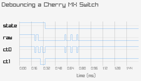
This figure shows the debouncer in action. The raw line is the direct output
of the pin; state, ct0, and ct1 are the values of the debouncer variables.
The readings are performed in a tight loop without sleeps, so this is the
fastest frequency I could read from the pin. One can see that the ct0 is set,
but is immediately reset whenever the raw line bounces. After that, there is
now enough confidence of the state change and the pair ct1 ct0 go from 11 to
00, flipping the state bit.
This is reassuring, but if we care about correctness we need a specification. The best specification I could come up with was these two properties:
- A flip only occurs after four consecutive disagreements.
- If four consecutive disagreements occur, a flip must eventually occur.
4. Conclusion
The two properties above fully describe the user-visible behavior of a correct debouncer and can be used to create a strong set of test cases for a real implementation, tracking all keys. I’ll report about that next time.
More references:
- Here I found the debouncer code: https://www.avrfreaks.net/s/topic/a5C3l000000U9zBEAS/t052183
- Further variants of debouncers are discussed at length here: https://www.mikrocontroller.net/articles/Entprellung
- And there is also a fully hardware-based implementation of the debouncer here: https://www.mikrocontroller.net/attachment/125089/Debounce.pdf
Bonus material: Modeling Debouncer with TLA+